by Dr. Nobie Stone
(See biographical sketch)
https://www.marshallretirees.org/orgiginal-memorial-database/person-detail/?pdb=45973
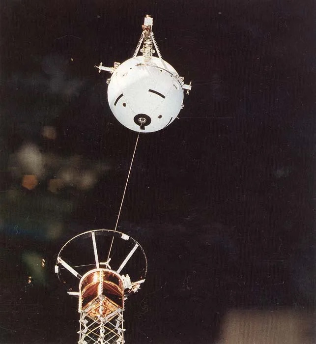
In 1985, Dr Stone was asked to serve as Project Scientist for the development of the joint US-Italian Tethered Satellite System (TSS). He then served as Mission Scientist for the flight of the TSS on Space Shuttle missions STS-46 in 1993 and STS-75 in 1996. The following account is based on his observations of the TSS program over its decade-long development and two space missions. The TSS missions involved deploying a specially designed satellite on a 12-mile long tether, which was about the diameter of a boot lace. The tether contained a bundle of copper wires so that the Space Shuttle Orbiter and the satellite, which was deployed upward from the Shuttle payload bay, would be electrically connected.
As the 12-mile long conducting tether moved through the magnetic field of the earth at an orbital speed of 18,000 miles per hour, the TSS would become a giant electric generator—employing the exact same principle on which an electric generator operates here on earth—and would create an electric potential (or voltage) between the satellite and the Shuttle Orbiter.1 The magnitude of the voltage that would be generated was easily calculated from basic principles—the amount of current that would flow in the tether, however, would be a complex function of the electrical conductivity of the tether, solar radiation intensity, the characteristics of the ionospheric plasma, parameters of the Space Shuttle’s orbit, and the TSS design characteristics.
The problems encountered during the TSS-1 and TSS-1R missions are well documented—less so what was learned of complex orbital dynamics, spacecraft charging, current collection by highly biased satellites in high altitude orbits, and new advanced in-space propulsion technologies. Herein, we will focus on what was learned from the Tethered Satellite program.
The TSS carried a dozen experiments (see Table 1) that were selected from US and Italian institutions, and was supported by a team of more than a hundred scientist from half a dozen countries. The various measurements were designed to work together in concert as one unified “experiment,”—much in the manner that an experiment is conducted in the laboratory, where a number of different factors must be measured with various instruments and the results combined to understand the phenomenon being studied.1 This required the TSS Science Investigator team led by Dr Stone to coordinate the design and operations of the various instruments—together with the Space Shuttle operations—to ensure that all measurements necessary to study the various phenomena associated with the electrodynamic tether were obtained. The TSS Program also included a coordinated one-year post-mission data analysis effort.
Table 1: TSS-1 and -1R Science Experiments
Experiment Principal Investigator Institution
Core Equipment (CORE) Carlo Bonifazi Agenzia Spaziale Italiana
Research on Orbital Plasma Nobie Stone* NASA/Marshall Space Flight Ctr
Electrodynamics (ROPE)
Research on Electrodynamic Marino Dobrowolnyǂ Consiglio Nazionale delle
Tether Effects (RETE) Ricerche/Instituto Fisica Spazio
Magnetic Field Experiment Franco Mariani Second University of Rome
for TSS Missions (TMAG)
Shuttle Electrodynamic Peter Banks1/ University of Michigan
Tether System (SETS) Bryan Gilchrist1R
Shuttle Potential and Return Marylin Oerhardt1/ Dept. of the Air Force, Phillips
Electron Experiment (SPREE) David Hardy1R Laboratory
Tether Optical Phenomena Stephen Mende Lockheed
Experiment (TOP)
Investigation of Electromagnetic Robert Estes Smithsonian Astrophysical
Emissions for Electrodynamic Observatory (SAO)
Tether (EMET)
Observations at Earth’s Surface Giorgio Tacconi University of Genoa
of Electromagnetic Emissions
by TSS (OESEE)
The Investigation and Meas- Gordon Gullahorn Smithsonian Astrophysical
urement of Dynamic Noise Observatory (SAO)
in the TSS (IMDN)
Theoretical and Experi- Silvio Bergamaschi Institute of Applied Mechanics
mental Investigations of
TSS Dynamics (TEID)
Theory and Modeling in Support Adam Drobot Science Applications
of Tether Satellite Applications International Corp. (SAIC)
(TMST)
*NASA Mission Scientist; ǂASI Mission Scientist
Electric Generator Mode Operations
On the TSS-1R mission, flown in 1996, during “generator mode” operations, the motion of the TSS through the earth’s magnetic field created an electric potential between the tethered satellite and the Space Shuttle Orbiter greater than 1,000 volts. This caused an electrical current of more than one Ampere to flow through the tether, which generated more than 1,000 Watts of electrical power.2
The electrodynamic tether had converted the kinetic energy of the Space Shuttle’s orbital motion directly into electrical power. This demonstrated that spacecraft orbital momentum can be used to provide the electrical power required to operate space missions. The power would be generated at the expense of the spacecraft’s orbital velocity, but the lost speed could easily be regained with a short thruster burn.
These results also confirmed earlier suggestions that the loss of orbital velocity, or drag created by an electrodynamic tether can be used to de-orbit a spacecraft, thereby eliminating the need to carry and store extra propellant to enable controlled re-entry at the end of a mission. The mass savings could then go to increase the payload.
Electric Motor Mode Operations
The results further showed that a high-voltage power supply can be used to drive a current through the tether in the opposite direction. In this mode, instead of generating electrical power, the tether system behaves like an electric motor, creating a force on the tether in the direction of orbital motion. The result is an accelerating thrust on the spacecraft that is produced without burning propellant, as would be required by a rocket motor. Further, if solar cells are used to run the power supply that drives the current in the tether, the energy required for acceleration is obtained directly from solar radiation and the tether “electric motor mode” thruster requires virtually no fuel. (A small amount of gas may need to be injected into the satellite’s environment to increase electrical contact and allow the required current to flow between the satellite and the ionosphere.3)
Note that both, the electric generator and the electric motor operational modes of an electrodynamic tether can be used to control the orbit of a spacecraft at any planet that possesses a magnetosphere—in other words, any planet that has a planetary magnetic field and an ionized layer of gas in its upper atmosphere.
High-Voltage Charging Effects
The TSS experiments led to an improved understanding of the “spacecraft charging problem” that had long plagued high-altitude satellites in synchronous orbits, causing them to behave erratically. The electrical bias on the TSS satellite could be swept, allowing the satellite-ionospheric interaction to be studied at high voltages—well beyond the capabilities of the laboratory simulation studies.2 This led to the realization that a theoretical model that had been relied upon for decades to describe the way a spacecraft charges up when exposed to the space environment that exists 10 to 20 thousand miles above the earth—was incorrect.4
In-Space Propulsion Applications: The Electric Sail
Space tether technology can enable more rapid interplanetary travel, where the tether system serves as an “Electric Sail.” The idea of a sail is that it “catches” the wind, transferring its momentum to the ship. In a similar way, an “Electric Sail” would use a spinning array of radially deployed wires several kilometers in length (geometrically similar to the spokes of a bicycle wheel) to intercept the solar wind—a hypersonic stream of ionized gas blown out into space by the Sun. The radial wires would be kept taught by the centrifugal force produced by the spinning motion of the system. Since the solar wind particles are electrically charged, they would be deflected by the electric field surrounding the charged wires, resulting in a loss of momentum by the deflected particles that would be transferred to the “sail and, therefore, the spacecraft.”
Although the array would be more than 98 percent transparent (thereby minimizing its mass), the electric field created by an electric potential applied to the wires would extend out radially, increasing the effective diameter of each wire (and, therefore, the area over which the solar wind particles will be deflected) by a factor of 1,000 to 10,000, depending on the applied voltage. As a result, the number of charged particles deflected and, therefore, the thrust produced, would be increase by the same factor. This also means that the level of thrust can be controlled by varying the voltage applied to the array.
Since the solar wind speed can be as high as 700 kilometers per second (420 miles per second—or about 1.5 million miles per hour) and extends out beyond all of the planets, even though the thrust force developed is very small (in the range of mille-pounds), when applied over a number of months, the “top end speed” speed reached by a spacecraft using such a propulsion system would be enormous compared to that of a chemical rocket.
Calculations based on earlier theoretical models of spacecraft charging and current collection predicted a rather modest benefit from using an electric sail. However, as mentioned above, a more detailed understanding of charging effects (first obtained from early laboratory simulations and, later, corroborated in space by measurements made during Spacelab-2 and TSS) showed this model to significantly underestimate the effects of charging.
Using the results of the laboratory and in-space measurements, the calculated thrust produced by an electric sail was found to be significantly greater and provided proportionally faster transfer times. For example, the Voyager-1 spacecraft, using chemical rocket propulsion, took thirteen years to reach the orbit of Pluto, and about 30 years to reach the heliopause (the boundary of the solar system where the influence of our Sun is matched by that of the interstellar medium). However, a satellite using Electric Sail Propulsion could leave earth and pass through the heliopause in only seven years—an important difference if you are an investigator waiting for data return!
Electrodynamic tethered satellites have tremendous potential for technological applications that will be “enabling” for some types of space missions.
References
1. Dobrowolny, M. and N. H. Stone, A Technical Overview of TSS-1:The First Tethered-Satellite System Mission, Il Nuovo Cimento 17C, 1, (1994).
2. Stone, N.H. and C. Bonifazi, The TSS-1R Mission: Overview and Scientific Context, Geophys. Res. Letters 25,409, Feb. (1998).
Stone, N. H., The Plasma Wake of Mesosonic Conducting Bodies: Part-1, An Experimental Parametric Study of Ion Focusing by the Plasma Sheath, J. Plasma Phys. 25, 351 (1981).
Stone, N. H., The Plasma Wake of Mesosonic Conducting Bodies: Part-2, An Experimental Parametric Study of the Mid-Wake Ion Density Peak, J. Plasma Phys. 26, 385 (1981).
Stone, N.H. and U. Samir, Bodies in Flowing Plasmas: Laboratory Studies, Adv. Space Res. 1, 361 (1981).
3. Stone, N. H., Development of a Solid-Expellant Plasma Contactor (SOLEX): Harnessing the TSS-1R Tether-Break Physics, Paper SPS VIII-04, JANNAF, 2005.
Stone, N. H., Electrodynamic Tether Operations Beyond the Ionosphere in the Low-Density Magnetosphere, presented JANNAF Propulsion Meeting, 2006.
4. Thompson, D.C., C. Bonifazi, B.E. Gilchrist, S.D. Williams, W.J. Raitt, J.-P Lebreton, W.J. Burke, N.H. Stone, and K. H. Wright, Jr., The Current-Voltage Characteristic of a Lage Probe in Low Earth Orbit: TSS-1R Results, Geophys. Res. Letters 25,413 (1998).
Wright, K.H., N. H. Stone and U. Samir, A Study of Plasma Expansion Phenomena in Laboratory Generated Plasma Wakes: Preliminary Results, J. Plasma Phys.33, 71 (1985).
Stone, N. H., K. H. Wright, Jr., U. Samir, and K. S. Hwang, On the expansion of ionospheric plasma into the near-wake of the Space Shuttle Orbiter, Geophys. Res. Lett. 15, 1169,1988.
